
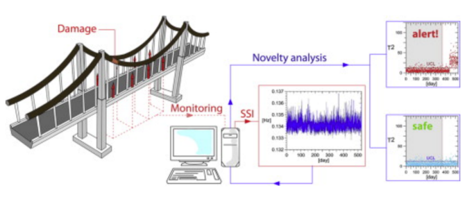
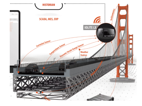
Bridge & Culvert Deformation Monitoring Solution
Using distributed fibre-optic sensing, drawing on (i) Brillouin-based DSS for long-range strain/temperature fields and (ii) OFDR-multiplexed multi-core FBG shape sensing where curvature/deflection reconstruction is required at high spatial fidelity; principles, governing equations, engineering methods, and a referenced field case are included.
1. Sensing principles
1.1 Brillouin DSS (BOTDA/BOTDR) — distributed strain & temperature
Along a bonded sensing cable, the Brillouin frequency shift Δf_B varies approximately linearly with mechanical strain ε and temperature T:
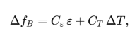
where Cε and CT are the strain and temperature coefficients determined by calibration; separation of thermal and mechanical components is achieved via (a) a colocated distributed‐temperature channel (DTS) or (b) a nearby thermally coupled but mechanically isolated reference run used to solve the two-unknown system, yielding the axial strain field ε(x) along the member.
From strain to curvature (beam theory). For a prismatic Euler–Bernoulli member of thickness hh with fibre bonded at distance zz from the neutral axis (NA), the bending curvature is
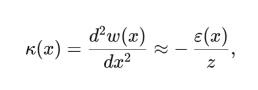
and bending stress σ(x,z)=E z κ(x); integrating κ(x) twice with appropriate boundary conditions gives the deflection w(x).
Culvert ring deformation. For a thin circular ring (radius R, thickness t), circumferential (hoop) strain at crown/springline/invert relates to ovalisation; if two fibres are bonded on intrados at orthogonal quadrants, the ovalisation index η may be approximated from differential hoop strain Δεθ as

(small-strain, thin-ring, elastic)
This provides a direct health indicator for culverts under soil–structure interaction and traffic load.
1.2 Multi-core FBG (OFDR) “shape sensing” — curvature vector & 3-D reconstruction
A tri-core fibre with FBG triplets provides three colocated axial strains εi at core positions ri (equilateral triangle, radius r from fibre centroid). The curvature vector κ(s) at arc-length s follows from
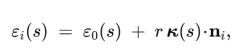
with ni unit normals from centroid to each core; solving the over-determined system (least squares) yields κ(s), then the centreline is recovered via Cosserat/Frenet integration (with an initial pose), segment-by-segment along the fibre. OFDR provides centimetre-scale virtual sensor spacing and sub-millimetre shape precision; care is needed for torsion and orientation calibration, since twist induces apparent out-of-plane error and endpoint errors can accumulate with arc-length, both observed and mitigated by alignment/calibration routines.
2. Engineering method (how we deploy and compute)
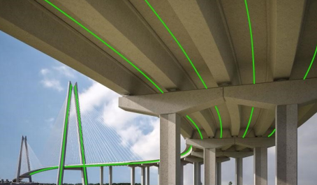
2.1 Layout & bonding
· Bridges (girders/deck): run DSS on the tension and compression faces of main girders (e.g., soffit midspan for sagging; web/diaphragm lines over supports), add a reference thermal run in the same micro-climate but mechanically isolated for ΔT separation; typical spatial resolution 0.5–1.0 m, gauge length 5–10 m for BOTDA.
· Culverts (rings/portals): place DSS circumferentially at crown, springlines, invert (intrados), plus axial runs near haunch/toe if settlement is expected; add short radial links to capture shear transfer across joints.
· Local shape zones: where rotation/curvature hot-spots are expected (e.g., mid-span, diaphragm cut-outs, joints), embed short MCF-FBG shape sensing segments (0.5–5 m) to directly resolve κ(s) and verify beam-theory curvature inferred from DSS.
Bonding & strain transfer. Use structural epoxy or asphaltic mastics compatible with substrate; provide anchor pads at 1–2 m to prevent peel-off, maintain minimum bend radius per cable datasheet; qualify strain transfer via pull-off tests on coupons.
2.2 Temperature–strain separation & QA
Implement a dual-run method (DSS_bonded vs DSS_free):
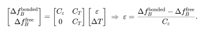
Validate coefficients with on-site thermal soak and static load checks; establish repeatability metrics (e.g., NRMS of repeated traverses) as acceptance criteria.
2.3 Curvature & deflection reconstruction (bridges)
With fibre at known offset z from NA, compute κ(x)=−ε(x)/z; then recover deflection by double integration with boundary conditions (e.g., for a simply supported span: w(0)=w(L)=0, rotations free). Numerically, use spline-fit κ and enforce boundary constraints by Lagrange multipliers or least-squares with penalty terms to suppress drift. Where available, MCF-FBG curvature at a hotspot can be fused (Kalman/weighted LS) with DSS-derived κ to reduce bias.
2.4 Culvert ovalisation & settlement diagnosis
From the three circumferential DSS runs, compute hoop strain εθ(θ); derive ovalisation index η and differential settlement signature (crown tension + invert compression vs springline) and track trends versus traffic and groundwater level. Flag thresholds may be set on ∣Δεθ∣, η, and their 7/30-day drift rates.
2.5 Instrumentation & operations
· Interrogators: BOTDA with reach to 10–50 km and ≤1 m spatial resolution; for shape zones, OFDR interrogator with cm-scale virtual sensors; keep instrument class constant across campaigns to avoid “pseudo-4D” biases and perform cross-instrument amplitude/phase match if replacement is unavoidable.
· Acceptance test: controlled truck-load run or jack-down test to verify κ and w(x) against LVDTs/total stations.
· Data services: real-time alarms, trend dashboards, and evidence packs for owners/insurers, with event replay and uncertainty bars.
3. Referenced field case & expected performance
Bridge case (cable-stayed, long span). A DSS system over ~10 km with 0.5 m resolution captured live-load peaks at mid-span; heavy-vehicle passages produced a peak stress proxy equivalent to ~85 MPa and ~30 Hz dynamic component, triggering overload alerts and informing traffic restrictions—demonstrating that distributed curvature and deflection can be reconstructed with sufficient fidelity for operations.
Culvert case (rail). Intrados runs over ~2 km detected a localised strain anomaly ~0.1%, temperature-corrected and diagnosed as ground settlement–driven ovalisation; targeted reinforcement prevented progressive damage—validating the ovalisation index and settlement signature as practical KPIs for maintenance planning.
Methodological caveats and mitigations. Orientation drift and torsion in shape zones can inflate out-of-plane error and endpoint accumulation; enforce anti-twist packaging, fix the first sensor triplet, and apply re-alignment routines as per OFDR shape-sensing practice; use denser virtual sensors where curvature varies rapidly.
4. Deliverables & KPIs
· Deliverables: distributed strain/temperature maps; curvature/deflection profiles; culvert ovalisation indices; alarmed dashboards; acceptance & MRV-style evidence packs (repeatability NRMS, calibration coefficients, uncertainty budgets).
· KPIs:
o Strain/temperature separation error ≤ specified % of full scale;
o Repeatability NRMS on control segments after temperature correction;
o Curvature–deflection closure vs survey instruments within agreed tolerances;
o Ovalisation index trend limits and 7/30-day drift thresholds.

 Prev
Prev
 Next
Next
 To list