
Fibre-Optic P&A Integrity Solution
Purpose and scope
Within the sequence spanning cement plug placement, remedial squeeze and TOC confirmation through to barrier verification, permanently or semi-permanently installed fibre is employed to:
(i) visualise and quantify in real time the cement return and setting process—deriving TOC, setting window and any under-filled intervals
(ii) diagnose the mechanical coupling state of the casing–cement–formation composite and the associated propensity for micro-annulus or channel-driven crossflow,
(iii) detect and localise passive and actively stimulated acoustic energy indicative of annular leakage within the bore and the near-wellbore, and
(iv) assemble a monitoring, reporting and verification (MRV) dossier whose evidential chain, repeatability statistics and tests of significance withstand regulatory scrutiny in the context of barrier verification at abandonment.
Monitoring mechanisms and observables
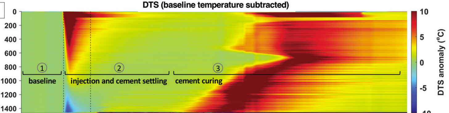
DTS (temperature) — cement hydration and fluid interfaces. Because cement hydration generates a transient exotherm in T(z,t)T(z,t) which rises to a peak and then relaxes, and because displacement fronts introduce step-like thermal contrasts, TOC and set timing can be inferred by criteria based upon the temporal gradient ∂T/∂t\partial T/\partial t, the integral of the excess heat and a “half-cooling time” threshold, which in combination yield depth–time bounds on placement and set without intrusive logging.
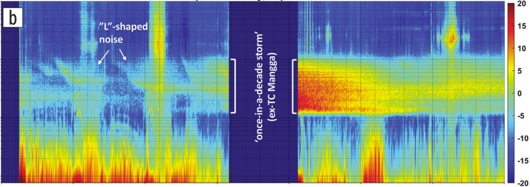
 DAS (vibro-acoustic) — coupling and leakage. As the casing–cement–formation system transitions from poorly bonded to well coupled, both the amplitude–frequency character and the arrival-time consistency of tool- or flow-generated wavefields recorded on DAS alter in a systematic manner; accordingly, pump noise, controlled surface sweeps or broad-band leakage noise under shut-in can be exploited to compute a coupling index—e.g., a matched-filter, post-stack RMS ratio and coherence metric—and to perform depth localisation of leak-related energy.
 Deployment windows and wellsite integration
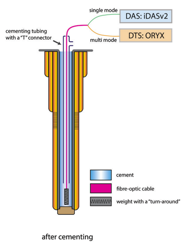
The preferred configuration places permanent single-mode fibre outside casing during remedial cementing or tail-pipe cementing, with vertical coverage extending typically 200–300 m above and below the intended plug/packer interval, whilst a single-use fibre probe run on slickline or as a drop-in can traverse the anticipated plug top and adjacent annuli to provide short-duration DTS/DAS confirmation where permanent fibre is absent; during displacement/returns the DTS+DAS stream is acquired online to capture interfaces and TOC, during hydration/set a 24–72 h period of higher-cadence DTS resolves the exotherm and set completion thickness, and during barrier verification both passive listen and active stimulation (surface sweeps or controlled pump excitations) are conducted to derive coupling indices and leakage fingerprints in terms of bands, modulations and coherence.
Processing and acceptance criteria
TOC and set (DTS). TOC is flagged where T(z,t) exhibits a time-gradient step or slope break co-located with a return interface; set completion is declared when the post-peak cooling half-time meets a threshold and the heat-integral stabilises, yielding a TOC depth with uncertainty and a set completion window suitable for handover.
Coupling index (DAS). For standardised operating segments, monitor–baseline pairs are cross-equalised with a matching filter, after which the RMS ratio and inter-trace coherence constitute a coupling index wherein decoupled or de-bonded intervals present attenuated amplitudes, depressed coherence and spectral distortion; where available, these intervals are reconciled against CBL/USIT for archiving.
Leak localisation (DAS). Under shut-in and steady-pressure conditions, short-window RMS mapping and inter-channel cross-correlation along the fibre—coupled with an acoustic-velocity estimate—yield a leakage centroid and an influence envelope, while A/B tests using valve actuation or micro-injection furnish corroboration.
Long-term deformation (DSS). Dual-run inversion separates ε and ΔT so that depth-dependent strain gradients across the plug and their daily/seasonal drift rates trigger alerts for barrier relaxation or re-loading.
Deliverables and KPIs
Deliverables comprise TOC and set time–depth panels, interval maps of filled versus suspect channels and de-bonded zones, leakage spectrograms with depth picks, casing–cement coupling-index curves, and long-term strain–temperature trends, all assembled into an MRV-ready abandonment integrity pack with repeatability (e.g., NRMS), cross-equalisation QCs and statistical significance tests for observed differences; illustrative KPIs include a TOC depth uncertainty of ±10–20 m conditional on well geometry, a set-completion window of ±6–12 h, statistically significant coupling-index changes at p < 0.05, leak-location windows of ±10 m given adequate SNR, a zero-incident objective over 6–12 months post-abandonment (or an incident-closure SLA), and demonstrable data provenance through monitor–baseline NRMS thresholds (for example, ≤ 30 % after matching).
Value proposition — why fibre is the most rational choice for P&A
By turning the abandonment interval into a continuously sampled section rather than a sparse set of discrete measurements, and by exploiting the inherently superior time-lapse repeatability of DAS/DTS relative to repeated perforation or mechanical logging passes, fibre enables multi-stage verification (from displacement through hydration to shut-in) with minimal intervention and disturbance, most operations being executed from surface with interrogators, sources and pumps, thereby aligning with the P&A imperative of simplified operations underpinned by robust evidence, whilst also delivering an integrated evidential chain—TOC, set, coupling, leakage and long-term deformation—capable of meeting barrier-verification audit requirements without serial tool runs.
Risks and mitigations
Near-surface variability and instrument changes that would otherwise manifest as pseudo-4D artefacts are controlled by deterministic deconvolution and matching-filter cross-equalisation tied to direct arrivals or pump noise, with cross-instrument amplitude–phase calibration mandated where interrogators are replaced; weak hydration signals or thermal cross-talk are countered by increased temporal sampling and the use of dynamic-strain indicators (DDSS) as an interface co-check; sensitivity loss under poor coupling is reduced by prioritising outside-casing permanent fibre across critical intervals and, where this is infeasible, by deploying single-use fibre to traverse the plug top for short-term confirmation.

 Prev
Prev
 Next
Next
 To list